CPS2 repair - battery damage
Categories:
[blog]
Tags:
[arcade],
[repair],
[cps2]
Board death
My friend recently pulled a CPS2 game board off the shelf and heard a rattling sound. Then noticed a weird brown fluid dribbling out the fan slots. Upon opening the case, the culprit was clear: the 1/2AA lithium battery had disintegrated, dislodging itself from the board and distributing its caustic internals all over the place. Despite his best efforts to clean up the board (using isopropyl alcohol), it wasn't in any playable state, and gave it to me to try to resuscitate.
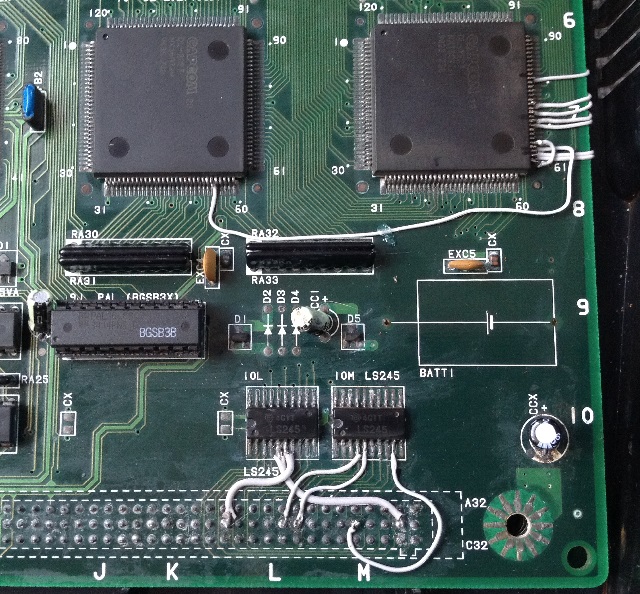
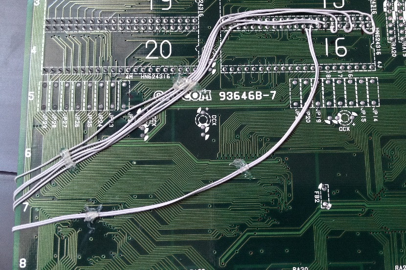
There was noticable corrosion on many chips, including the CGA chip which interfaces with the graphics ROMs. Using a multimeter, some of the obvious breaks in continuity were found, but corrosion makes soldering difficult. I used a brass wire brush on the CN4 header's solder points to strip back some of the corrosion, then used some solder flux and a very hot soldering iron to regain SOME kind of solderability to the connections. It still wasn't easy. A similar (but more careful) cleaning was necessary on the LS245 chips nearby to allow soldering to their legs again, then kynar wire was used to rejoin the PCB traces that were broken. At this point the obvious stuff was fixed, so I gave it a boot.
CPS2 boards have a 'suicide battery', which once has been drained or dislodged for a half hour or so, causes the board to lose some vital decryption tables and renders the game useless. Since the battery in this board had been literally rolling around inside the case, this board had suicided. Fortunately, a 'phoenixing' (i.e. bringing back to life) process has been made available, which involves burning custom EPROM chips containing already decrypted data and installing them into the board. Also, a test EPROM is available to show whether the board in question has in fact suicided. I put this chip in, and was greeted by music playing as expected. Unfortunately the graphics were extremely garbled, although I could see enough to tell that the board was roughly functioning correctly - and the music also made this more likely.
So, now the hunt was on for the rest of the problems with the board.
Finding problems
To aid in such a search, I highly recommend a logic probe. They are cheap, and when connected to the +5V and GND of the powered board, allow you to test each pin and see if they are High (+5V), Low (GND), Pulsing (switching rapidly), or, most importantly, nothing - which is to say, disconnected. Using this tool I found several points on the CN headers which were disconnected, and also ROM chip legs that were not creating the correct contacts.
Great, so having located some more problems, how do you know where these broken connections are supposed to go? Sometimes you can see the trace easily, but often the traces weave between the various layers of the board, or are hidden from view by connectors, chips, etc. What is therefore invaluable is a working (or close to working) board which you can use a multimeter on to find where the traces ought to end up. It can still be challenging tracing these connections though, but dilligent testing and a bit of intelligent guesswork can make it easier. Using another CPS2 board, I made a spreadsheet with most of the relevant pins traced out, which you can find at CPS2 repair spreadsheet. Please note I've only filled out the pins which I needed to to fix my problem, there are absolutely gaps. If anyone has any additions or corrections, or needs some help, please tweet or email me.
There are possibly some terms I've used which need some explanation:
CNx refers to pin header x between the A and B boards. These are the big 3-row connectors.
ROMBANK (x) means the set of 4 ROM slots positioned at x on the board (there are grid coordinates stamped on the edges of the board, A-M and 1-10).
Where destination pins differ depending on which ROM is used within the bank, it's specified by
x for (ROM[s] y,z) - x' for (ROM[s] y',z').
I hope that's clear enough.
Any mention of CGA or CGD refer to the big square chips with 120 pins on the board, they are labelled on the board silkscreening.
Fixing
After that, it's a matter of cleaning the relevant pins of each end of the broken trace, and then using some kynar wire to recreate the connection. Kynar is great because it's very fine, and therefore easier to route around the board, and also better for soldering to small points/pins. The battery in the CPS2 board is very close to a chip with many small pins which undoubtedly will be damaged, so you'll probably need fairly decent soldering skills to repair those traces.
Here are a couple of pictures of the board after I've repaired it.
...and a video for good measure
Conclusion
Store your CPS2 boards label-side down! This will at least ensure if the battery leaks (or falls off), the corrosive fluids won't pool on the PCB and instead will drip onto the plastic case. Still not brilliant, but at least your board won't be damaged, causing you (or a friend) to spend countless hours fixing it!