SEGA Master System 1 VA3 PAL 50/60Hz mod
Categories:
[blog]
Tags:
[modding],
[master system],
[sega]
I was recently asked to modify a fellow's Master System 1 and add a 50/60Hz switch, so I had a look around at MS1 mods and found a nice and easy guide, which mentioned the solder points are clearly labelled 'NTSC' and 'PAL'. Upon opening this particular MS1, I found no such thing - but there was a silkscreen label showing that the model is a PAL VA3 variant. There are a few google hits for modding this version, but I thought I should add to that with some pictures.
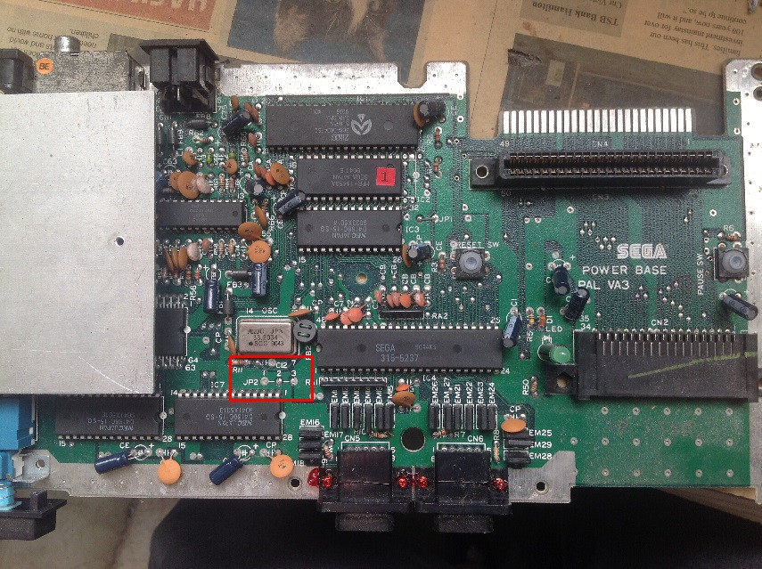
Here's the full motherboard PCB with the area of interest highlighted with a red rectangle:
And a close-up of the area:
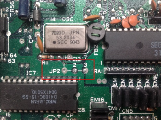
JP2 is the selector for whether the machine runs in 50 or 60Hz. Solder point 2 connects directly to the 315-5246 chip's pin 57, which cross-referencing to SMSPower's 315-5246 pinouts is indeed the NTSC/PAL selector for the video output. On a PAL board, this is hard-wired to +5V for 50Hz operation, which is solder point 3. Pin 1 is GND.
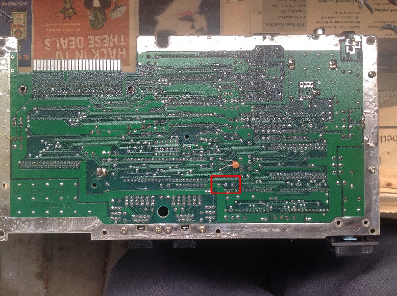
Here's the back-side of the PCB:
and a close-up, which shows the 3 solder points and also the trace which connects point 2 to point 3:
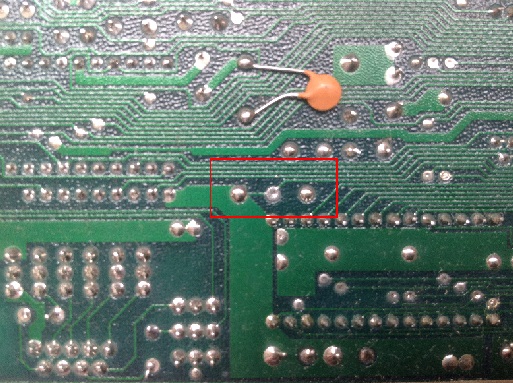
To perform the mod, this trace needs to be severed. Take a sharp stanley knife (read: box cutters) or similar knifey tool, and carefully cut a track across the trace. I like to make two parallel slices near to each other, and then peel out the section of copper trace in between, just to make sure. If you have a multimeter (and if you're doing this kind of operation, you really should!), use the continuity tester to confirm that points 2 and 3 no longer have continuity.
Next, solder a wire onto each of the points (for a total of 3 wires). It's probably best to remove the solder from the holes first (using a solder sucker or similar tool), then you can stuff a wire in the hole and solder it up, nice and securely. You can get away with just soldering the wire onto the solder point itself though.
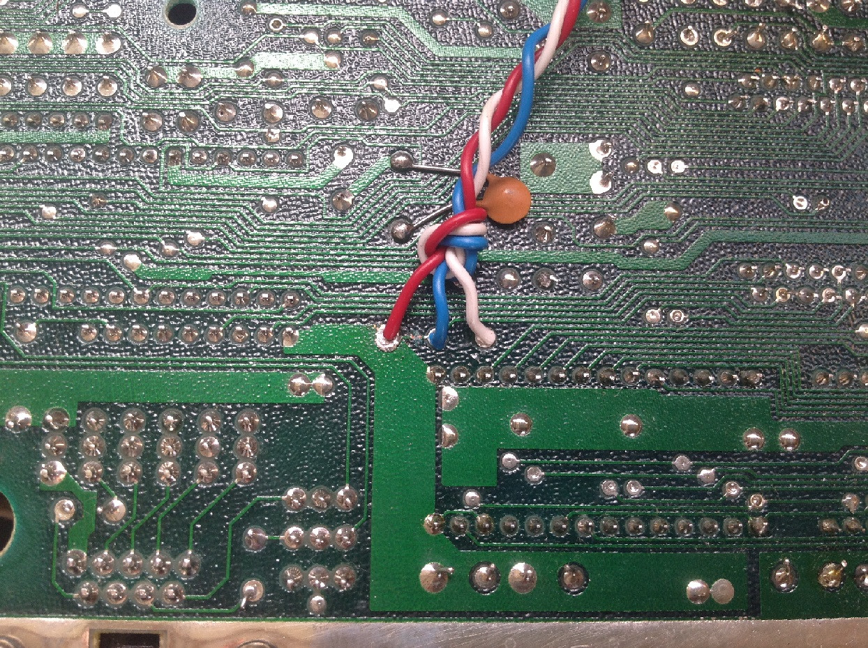
Here's a pic with the wires soldered in place, unfortunately the cut across the trace isn't particularly easy to make out due to the lighting, but it's certainly severed. Note the patriotic colours I chose, this is after all a PAL SMS1, so clearly the wires should reflect the colours of the Union Jack! Red for +5V, and White for GND.
Now route the wires to wherever the SPDT switch is/will be located - I chose the back corner opposite the power and AV ports. Make sure whichever wire you connected to the JP2-2 point is soldered to the MIDDLE leg of the switch (in my case, the blue wire). The other two wires go on the other legs, depending on which switch position you want to be 50Hz and which you want to be 60Hz.
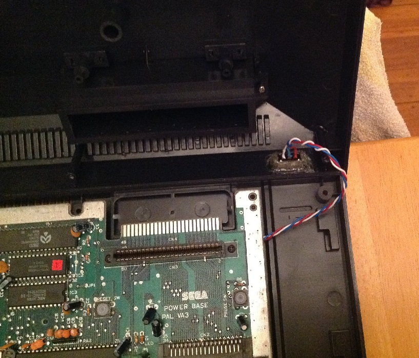
Here's a pic of my switch installed and wired up. This particular switch has no screw mount, so I just slathered some hot glue around the place to secure it. Not pretty, but functional.
That's pretty much all there is to it! If you want to be safe, do some tests with your multimeter - in particular, check there's no continuity between GND and +5V, with the switch in both positions. If there is, you've caused a short somewhere and need to fix it before applying any power to the system. Always pays to check for shorts, very quick & simple test that can save you a console if you buggered something up and just plugged it in!
Now enjoy your modded SMS in the full 60Hz glory it was intended!